Custom Slurry Hoses c/w Muff Couplings
For applications including hard wall suction and discharge hose, soft wall dishcarge hose in slurry pipe line, and specialty trunnion hose for suction cutter dredge. In addition to the high-wear-resistance rubber elastic inner liner, the ceramic tile inner liner can provide superior wear resistance.Expertly crafted to transfer of abrasive slurries, mineral processing.plants, tailings lines, sand and gravel. Other applications also available on engineering.
Features:
▪ Versatile design allows for the hose to be cut to length on site
▪ Coupling design supports multiple flange drill patterns
▪ Reusable split cast couplings to create a reusable flange connection
Benefits:
▪ Smooth or Corrugated hose cover for suction and delivery
▪ Adaptable open ended hose design for installation flexibility
▪ Swivel slotted flange design supports multiple drill patterns
Technical Specifications
| Hose Size | DN50– 600 (2–24") |
|---|---|
| Hose Lengths | Up to 12m |
| Pressure Rating | |
| -100 to 5000kPa | |
| Higher on request | |
| End Connections | |
| Cut end | |
| Inbuilt flange | |
| Flange Drill Patterns | ASME B16.5 150# |
| DIN 2501 PN 10/16 | |
| Custom | |
| Safety Factor | 4:1 |
| Extra options | Gaskets available |
| Couplings Segments | two or four |
Material Specifications
| Inner Liner | Abrasion resistant elastomer |
|---|---|
| Neoprene, SBR, or buty | |
| high alumina ceramic | |
| Reinforcement | Cord and spiral wire |
| Outer Cover | UV, ozone, and abrasion-resistant rubber |
| Muff Couplings | High strength aluminium alloys |
| Cast iron or high-grade alloy |
Standard Properties - Slurry Hoses
| Hose Size | Liner Thickness | Vacuum Rating | Working Pressure | Min Bend Radius | safety factor | |||||
|---|---|---|---|---|---|---|---|---|---|---|
| Std | Max | Std | Max | |||||||
| DN | in | mm | mm | mm | % | kPa | kPa | m | x Dia | ratio |
| 100 | 4 | 102 | 6 | 12 | 100 | 1000 | 5000 | 0.8 | 8 | 4:1 |
| 150 | 6 | 152 | 6 | 12 | 100 | 1000 | 5000 | 1.2 | 8 | 4:1 |
| 200 | 8 | 203 | 6 | 12 | 100 | 1000 | 5000 | 1.6 | 8 | 4:1 |
| 250 | 10 | 250 | 9 | 15 | 100 | 1000 | 5000 | 2 | 8 | 4:1 |
| 300 | 12 | 300 | 9 | 19 | 100 | 1000 | 5000 | 2.4 | 8 | 4:1 |
| 350 | 14 | 350 | 9 | 19 | 100 | 1000 | 5000 | 2.8 | 8 | 4:1 |
| 400 | 16 | 400 | 12 | 19 | 100 | 1000 | 5000 | 3.2 | 8 | 4:1 |
| 450 | 18 | 450 | 12 | 19 | 100 | 1000 | 5000 | 4.5 | 10 | 4:1 |
| 500 | 20 | 500 | 12 | 19 | 100 | 1000 | 5000 | 5 | 10 | 4:1 |
| 550 | 22 | 550 | 12 | 19 | 100 | 1000 | 5000 | 5.5 | 10 | 4:1 |
| 600 | 24 | 600 | 12 | 19 | 100 | 1000 | 5000 | 6 | 10 | 4:1 |
Customisable size available in non-standard specifications on request.
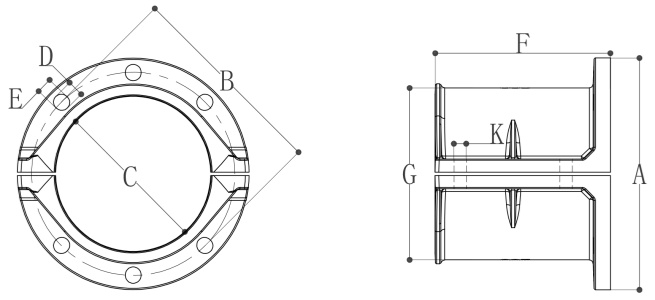
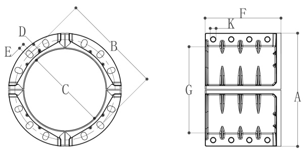
Standard Properties - Split Flange Muff Couplings
| Coupling Size | Segments | Drilling Pattern | Neck Dimensions | Matches Flange | |||||||||||
|---|---|---|---|---|---|---|---|---|---|---|---|---|---|---|---|
| OD | PCD | ID | Holes Size | Holes/Joint | Overall Length | OD | Hole Dia | Holes/Joint | DIN 2501 PN 10 | ANSI B16.5 150 lbs | |||||
| DN | in | mm | A | B | C | D | E | F | G | K | |||||
| 100 | 4 | 102 | 2 | 220 | 185 | 123 | 25 | 19 | 3 | 133 | 143 | 16 | 2 | 100 | 4” |
| 150 | 6 | 150 | 2 | 285 | 240 | 173 | 23.5 | 23 | 3 | 197 | 195 | 20 | 2 | 150 | 6” |
| 200 | 8 | 200 | 2 | 340 | 297 | 228 | 24 | 23 | 3 | 257 | 252 | 20 | 2 | 200 | 8” |
| 250 | 10 | 250 | 2 | 405 | 357.4 | 274 | 30 | 26 | 5 | 250 | 297 | 20 | 2 | 250 | 10” |
| 300 | 12 | 300 | 2 | 476 | 417.2 | 330 | 40 | 25.4 | 5 | 310 | 355 | 20 | 3 | 300 | 12” |
| 350* | 14 | 350 | 4 | 510 | 460 | 382 | 32 | 27 | 3 | 350 | 407 | 20 | 3 | 350 | - |
| 350* | 14 | 350 | 4 | 530 | 476.3 | 382 | 35 | 30 | 2 | 350 | 407 | 20 | 3 | - | 14” |
| 400 | 16 | 400 | 4 | 596 | 528 | 432 | 42 | 29 | 3 | 400 | 457 | 24 | 4 | 400 | 16” |
| 450* | 18 | 450 | 4 | 625 | 565 | 482 | 36 | 29 | 4 | 450 | 507 | 24 | 4 | 450 | - |
| 450* | 18 | 450 | 4 | 634 | 575 | 482 | 36 | 33 | 3 | 450 | 507 | 24 | 4 | - | 18” |
| 500 | 20 | 500 | 4 | 695 | 630 | 536 | 37 | 32 | 4 | 500 | 561 | 24 | 4 | 500 | 20” |
| 600 | 24 | 600 | 4 | 815 | 739.6 | 640 | 44.6 | 36 | 4 | 600 | 670 | 27 | 4 | 600 | 24” |
*350/450 sizes (marked *) have separate dimensions—they don’t fit both DIN 2501 PN 10 and ANSI B16.5 150 lbs flanges. Choose per your flange standard.
Send us a message
Free Samples
Trial Orders
Quick Quotes
Evaluate our products with small trial orders, request free samples to test quality, and benefit from rapid quotes tailored to your requirements.
Your email information will be kept strictly confidential and our business staff will ensure that your private information is absolutely safe!